SOLDERING
The Right Equipment
EQUIPMENT

First - you need to start with the right equipment. There was a time when you could use a thick, hefty screwdriver heated over hot coals to do soldering. That might be great for doing stained glass work, but if you try to use that on a transistor - you'll be buying a new transistor, and perhaps a whole new circuit board! At the same time, schools, parts manufacturers, and even employers will suggest that you purchase the most recent, most expensive soldering and rework stations known to mankind. If you follow their suggestions, you will doll out about $500 for a usable "solder work station". Will it do the job - depends on the job! Instead - I offer an inexpensive "comprimise", that will allow you to easily handle 90% of all electrical soldering you will encounter in your lifetime. Here it is:
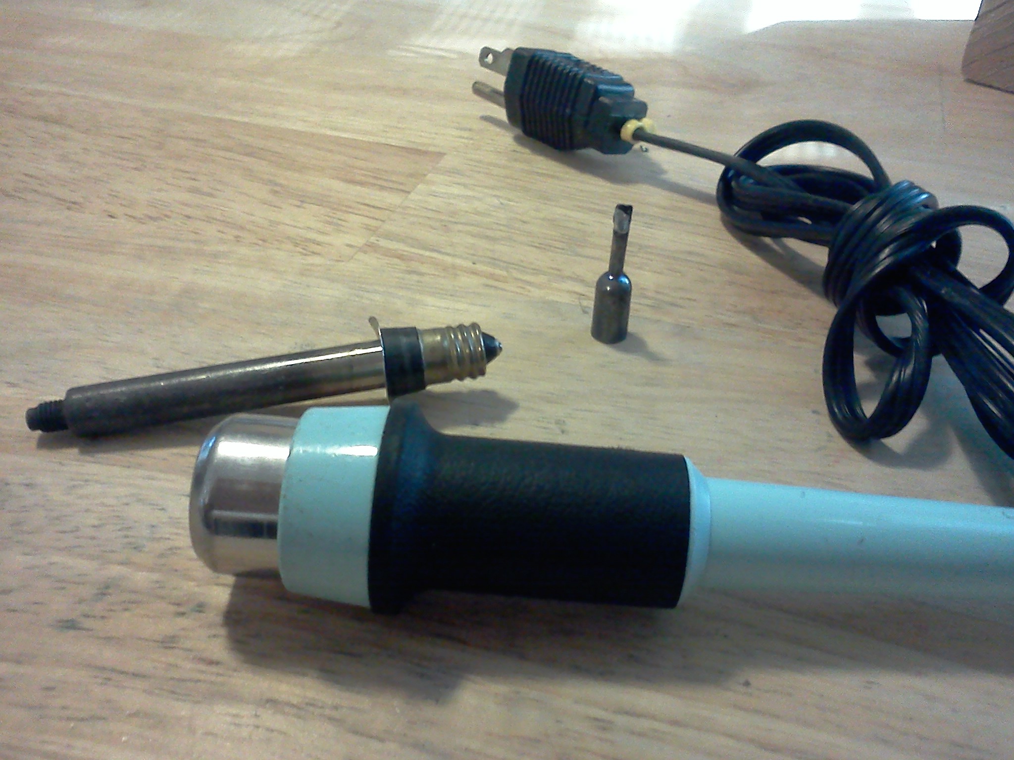
Begin with a MODULAR solder iron. Why modular? Because it is versital, because it configurable, and because it will serve you well for the rest of your life. You want a handle with a GROUNDED plug. I suggest something along the lines of a Weller 7400. (I use Weller numbers here for convenience and reference. Whether you use Ungar, or some other brand is not important. If the solder iron you get has the same specifications, you'll do fine.)
Put a 45 Watt Heating Element on the Handle, and finally a 1/8 inch "screwdriver" type tip. For reasons I'll explain later, pencil tips are only to be used for extremely fine soldering, and frankly - I find them useless. Chisel tips should be reserved for thick "Ground" soldering.
For your convenience - here is a parts ordering list. Again if you want to go with another brand, you'll be ok as long as the equipment you purchase matches the specifications of the equipment I have given:
- Weller 7400 Handle (or equiv with GROUNDED plug)
- 4037S Heating Element
- PL113 or PL151 Screwdriver tip (for general soldering) Personally I prefer the 151.
- PL133, PL153, or PL350 Chisel type tip (for heavy soldering) again - pencil tips are relatively useless for most soldering purposes.
A "Cool" Modification
One of the things I always thought was a pain was the warm up time for a solder iron. Also, sometimes (but not very often) you may want to use a cooler solder iron. A fix for both of these problems was a magic little box I made to go between my solder iron, and the wall jack.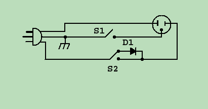 The box is a standard electrical outlet JBox with a power plug going in, an outlet jack, and 2 toggle switches. The Grounded 115 Volt power cord comes into the box. The green wire is grounded to the JBox chassis. The white wire is connected to the neutral side of an outlet jack (the silver screw - or the LARGE flat connector). The black wire goes to a SPDT toggle switch(S2). The two "outputs" of the toggle switch has a diode run from one ouput to the other, and the second output also has the black wire running to the "hot" side outlet jack (the gold screw). There is a second toggle switch (SPST S1) with one side connected to ground and the other side connected to the ground wire on the outlet jack. So from the outlet jack's point of view - it is connected to a toggle switch on the hot side (black), a toggle switch on the ground side (green), and the neutral (white) wire runs straight through.
 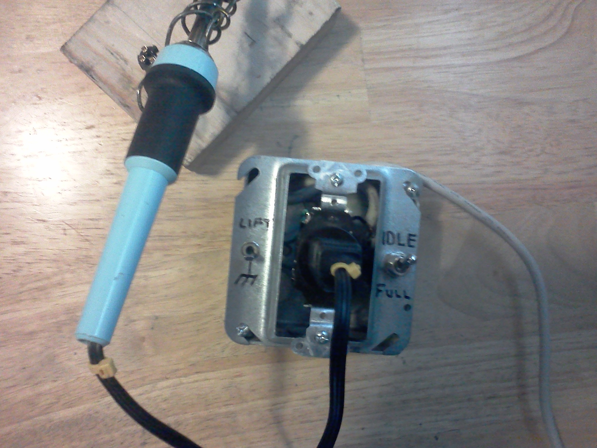 Basically, it works like this: You plug it into the wall, and plug your 45 Watt solder iron into it. One toggle switch is a "ground lift" for if you are soldering on "hot" grounded equipment. If you use a grounded solder iron on this equipment, and it happens to be plugged in - you are likely to take a healthy jolt, if not destroy the equipment. So the purpose of switch 1 is to remove this possibility by simply lifting the ground on the solder iron via a toggle switch(S1).
 The second switch (S2) is used as an "idle" switch. In its normal position, 115 Volts is applied to the "hot" lead of the solder iron, and allows the soldering iron to run at a full 45 Watts. When you flip the switch into "IDLE" mode, the diode kicks in and only allows 1/2 the Voltage to go to the iron, making it run at a lower voltage. Now your 45 Watt iron is running at about 1/2 heat (about 23 Watts), which makes it heat up to full temp much quicker when you flip the switch to its "FULL" position. As a side effect, in the IDLE position, it is very nice for use on heat sensitive equipment, where you might be told to use a 23-25 Watt iron. Also - in my particular case, I used a 3 position switch, and the third (center) position acts as an "off" switch. I thought about putting a light in line with the output so I'd know if it was on or off, but I decided not to. Another (wise) modification to this box would be to add a fuse in line with the INPUT side of the black wire (before the switch), so that if something should happen to go wrong with the internal wiring, it will simply pop the fuse. So with the simple addition of a toggle switch and a diode - you now have 2 solder irons. A 45 Watt, and a 23 Watt - both with an optional ground, and interchangable tips!
The Right Solder
There are several kinds of solder, and not all of them are suitable for electronics work. Solders can be categorized by Materials, hardness, melting point, and type of core. Materials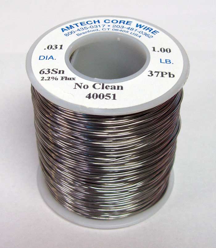 There are many materials that solder CAN be made from. Typically in electronics, a 60/40 mixture of tin and lead were used. Similarly a 63/37 mixture of lead and tin can be found. These are both moderate temperature solders that are easily used for electrical work.
There is a problem though. Lead is considered by experts to be a poison. I say it is "considered" a poison because while some "far better qualified than I" organizations which claim that as little as 10 micrograms of lead per deciliter of blood (μg/dL) is harmful (that's 1/100,000 of a gram per liter of blood), I've been handling lead in the form of solder for over 35 years, and show no signs or symptoms of lead poisoning. I think it might be poisonous if you eat it, although I've known kids that grew up quite healthy, who in their childhood used to peal lead based paint chips off the school room walls and eat it!
Well, I say that - but the symptoms are typically balding, headaches, abdominal pain, memory loss, kidney failure, and weakness, pain, or tingling in the extremities. It seems to me that with folks my age - most of those "symptoms" apply - even if we haven't played with solder. That being said - I only have abdominal pain when I eat jalepenos, show no sign of balding, and the only weakness, pain, and headaches I have can be atributed to a hard, stressful day at work.
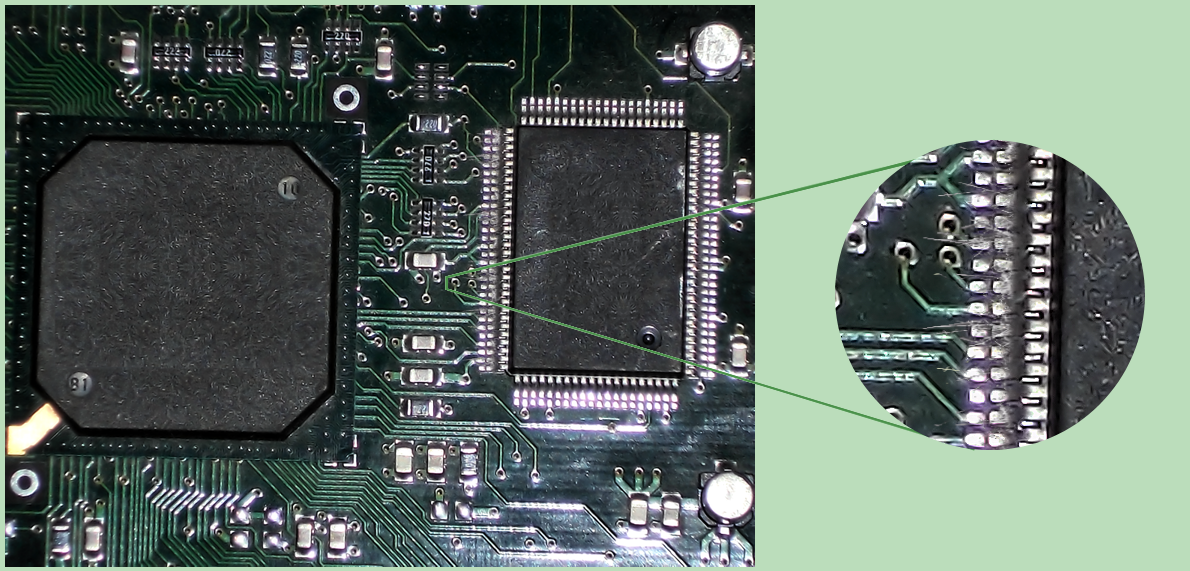 Nevertheless, because of these warnings, lead is being reduced in landfills, by reducing the amount used in electronics production. In short - newer "lead free" solders are being used nowdays which are harder to solder (requires more heat), and after some time developes "tin whiskers" on them which can affect radio frequency equipment and high speed computer systems adversely. So much for progress. As an interesting side note- lead based solder has also been banned from use in plumbing. I find this especially interesting, as the word plumbing comes from the Latin root word Plumbus, which is the Latin word for lead. Funny how plumbers don't use plumbus anymore because of fear based government regulation. In short - if you are afraid of touching lead - wear gloves.
**Politically speaking - (stepping up onto my political podium) Tin whiskers is a VERY REAL problem that proponents of RoHS compliance are afraid to discuss, because it is far more dangerous than the lead poisoning they are fighting to stop. Tin whiskers are the natural chemical result of crystalline growth of the metal tin in the absense of lead. "RoHS compliance" - an international push to get rid of lead in landfills has caused electronics manufacturers to curb the use of lead, which is now creating more of a tin whisker problem in the electronics world. It has been shown that Tin Whiskers was the cause of at least one $250,000,000 satellite to go bad in space (Galaxy 4) and are expected to cause even more problems. Tin whiskers can take place in the confines of space, and unseen inside the packaging of transistors and integrated circuits. Tin whiskers, due to RoHS compliance, are now able to be found in any kind of electronics anywhere in the world, including Military Weapons and Nuclear Plants, and the brakes on the car you drive use electronics. So when the Nuclear plant 20 miles from you, goes Fukishima, or the nuclear missile accidentally launches and lands and blows up in your home town and kills millions of people - you can blame it on the "save mother earth" people who are afraid of putting the lead back where it came from - the earth - because it might leach out and get in your water, and make me grow bald by the time I'm 60 years old.(steps down)
Whenever we change the metals that solder is made of, we also change its other physical properties, such as melting point and hardness. Some types of solder are specifically chosen for these properties. For instance - you want a hard lead when working with pipes, but a low melting point when working with sensitive microprocessor chips.
Solder comes in two types of core - Solid and Hollow. The solid is what it says it is - solid solder. The Hollow core type is a bit misleading. It isn't truly hollow. It is filled. Hollow core solder has some kind of FLUX in the middle of it. The purpose of the flux is to make it flow better. There are typically two types of flux found in the "hollow" core of solder. The first type is ACID core, which is absolutely NEVER to be used in any electrical work. It may be fine for plumbing or stained glass work - but acid core solder will eat circuit boards, destroy components, etc. Instead - ROSIN core solder is used in electrical work.
So, after all this babbling - what are you looking for in a solder? Well, if you plan on eating it - find something lead free. Otherwise, if you are going to do electrical work, you want Rosin Core 60% tin, 40% lead (60/40) or 63/37 will work just fine for MOST soldering you will be doing.
The Right Procedures
 There are several kinds of soldering equipment sold on the market because there are so many different kinds of soldering! People solder pipes, they solder stained glass, they even solder jewelry. What we intend to cover here is soldering of electronic equipment.
Before we get too far - lets get a firm grip on what soldering isn't, then we can better grasp what soldering is.
Soldering isn't bolting, screwing, riviting, or otherwise fastening. It is not intended to hold, bond, or otherwise keep things together indefinately. That is what nuts, bolts, and lock washers are for. If you don't want it to fall apart - don't expect solder to keep it together.
Soldering isn't welding. In welding you use heat to melt two different pieces of metal to their melting point, and join them so that they become one solid piece of metal. When you are done - you have a very mechanically sound connection that is stronger than using a nut and bolt!
In Soldering, you only melt ONE piece of metal to its melting point - the solder itself. And if done proplerly - you never touch the solder with the heat source! Soldering is by definition, "The heating of a base metal to a point to where the filler metal melts and fill the gap between two pieces of base metal.The base metal itself is NEVER melted, only the filler metal. Because the base metal is never melted, there is always a weak area between the two metals where mechanical stress can indeed break them apart - hence it is NOT considered to be a good mechanical connection.
GENERAL PROCEDURE
In doing ANY kind of soldering, there are some GENERAL practices that should be followed. The reasons for each of these procedures we will discuss in detail in a bit. I'll give you a list of the proceures first, and they HAVE to be done in order, or you will be risking a possibly bad connection, "cold" solder joint, or otherwise a problem that will cause your circuit to fail. Follow every step in this list, and you will be sure to make a good solder joint every time.- Confirm good mechanical connection
- Heat the Soldering Iron
- Test the Soldering Iron
- Clean the Soldering Iron
- Tin the Soldering Iron
- Heat the Connection (the base metal)
- Touch the Connection (the base - not the iron) with solder
- Watch for FLOW (you will see it flow like a liquid)
- Remove solder
- Remove heat
- HOLD STILL until cool (you will visibly see it solidify)
- Clean the iron.
Making the Mechanical Connection
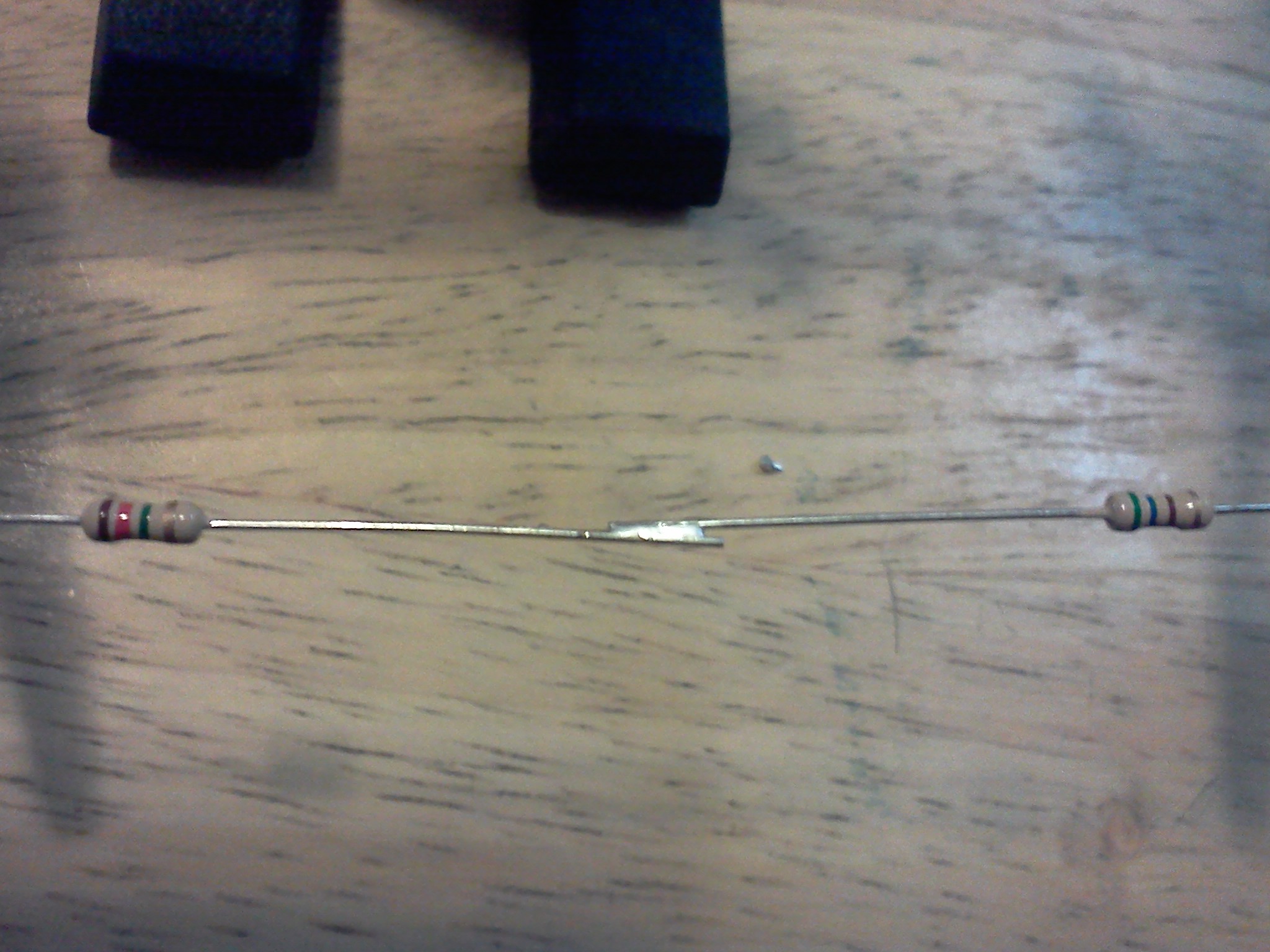
Lets assume you want to solder two resistor leads together. If you simply solder them together without twisting them, in any way, then any mechanical stress applied to the leads could easily pull them apart. This would be bad, especially if there is voltage applied to that wire at the time it comes loose!
An accepted procedure is to put "hooks" on the ends of the two resistors, and then pinch the hooks.
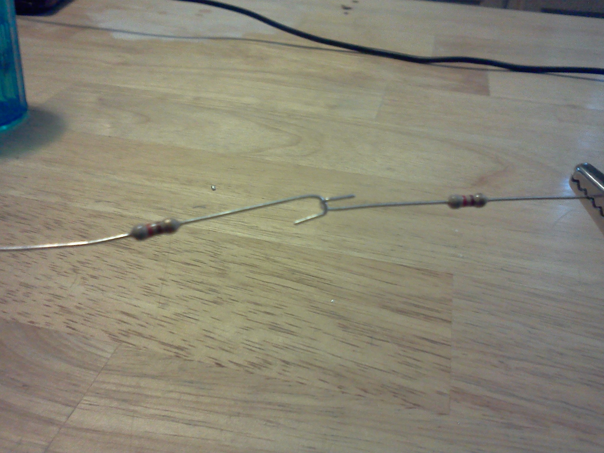 If you can lift one resistor with the other, and they don't move or come apart - then likely you can begin to solder them. Alternately, you can connect both resistors to some other connector, and put the hooks in the ends of the resistor through the connector, then solder both resistors to the connector.
After you have made the mechanical connection, it is time to heat up the solder iron. How fast your solder iron heats to a temperature that you can melt your solder depends on how many Watts your solder iron consumes. Gracefully put - the more Watts your iron has - the faster it will heat up. While you are waiting for your solder iron to heat up, (and assuming your solder iron is well supported and away from any flamable items), this would be a good time to get a cup of coffee, read some more of the course, or visit one of our sponsors (HINT) that pay for this page. Every click helps!
Though there are variations in types of solder - for electronic work, a 40/60-ish blend of Lead and Tin is used, giving a melting point of around 370°F (185°C).
There are "low temperature" solders (which we will discuss later) for sensitive work, and lead-free solders that require higher temperatures. Most solder irons will reach 600-900 degrees F. The 45W iron we suggest will easilly reach 900°F (480°C), and with the diode modification listed earlier which yields a "23 watt iron", you can achieve 700°F (370 °C).
Needless to say - if it is hot enough to melt metal (other than mercury), you likely don't want to touch it with your fingers, clothes, kitchen table, paper, or anything else that could catch your house or work area on fire or injure you. Consider this your necessary legal warning. What you do with a solder iron - is YOUR fault - not mine! Be sure to read any further warning lables on your particular soldering equipment and supplies!
Testing the Iron
If you happen to be fortunate enough to afford a high end solder station, yours may come with a built in temperature probe that tells you EXACTLY what the temperature of your iron is. Alternately, you could use any contact type temperature probe, or even an infra red temperature sensor to determine the exact temperature of your solder iron. I on the other hand, do not have hot and cold running money - so I use the following approach:SMELL - first, I smell the iron to insure that it indeed is warming up. Being careful, of course not to touch my sensitive skin with the iron, and making sure there are no smart aleks in the room that might pat me on the back. I do NOT do this once I've established that it is hot - only when I first turn the iron on to make sure it indeed is heating. It is horribly frustrating to wait 10 minutes or so for an iron to heat up, begin to do your work, only to find out that the iron is stone cold. (typical causes - you forgot to plug it in, turn it on, or possibly the heating element itself has died).
TOUCH - next, I touch the solder iron - not with my fingers silly - with the solder. If it begins to melt and flow on the iron - you are ready for work.
Clean and Tin
Now that we have a good mechanical connection, and a tested HOT soldering iron, it is time to begin soldering - almost.CLEAN the Iron (and all connections)
DON'T TOUCH THAT SOLDER until you are absolutely positively certain that everything is ready - and by ready I mean CLEAN! If bad is the opposite of good, then dirt is the opposite of solder. If either your solder iron, or your connection is dirty - you are going to have a heck of a time getting the solder to "stick" to it - no matter HOW hot your iron is!To clean off the connection - use whatever it takes - alcohol, rubber pencil eraser, sandpaper, Scotch Brite ® pad, heck I don't care if you use a (clean) brass bristle brush - just make sure all your connections are clean before you get started.
 To clean off your solder iron - try to be less drastic. Your solder iron is your friend - and on a battlefield - may save your life! While the iron is hot, wipe it with a WET sponge (water, not alcohol). If you don't have a sponge, you can substitute with a damp cloth, or even a damp paper towel. This should clean it off. If that doesn't work, "tin" the tip of the iron with a little bit of solder (remember - it is made of lead and tin), then wipe it with the sponge again. If this doesn't work after SEVERAL tries - you are down to a last resort. Let the iron cool down, then break out the file, and carefully (not losing the normal shape of the solder iron tip) file the grit off the tip, taking great care not to harm the tip itself. In some cases - this is forbiddingly destructive, as some tips are actually coated (electroplated) with REAL SILVER! However, in a pinch with the bombs going off around you - this will guaranteed clean off the tip of the iron. Do NOT forget to tin the iron immediately after you do this. As a side note - when cleaning the iron tip - sponges work best. No one knows why. Make sure whatever you use is clean and free of dirt or oil, and whatever you do - don't use your mom's table cloth!
Tin the Iron (and all connections)
 Tinning simply means putting a very light coat of solder on the tip of the iron. It helps the solder to flow quicker when you do get around to doing the actual soldering. You should tin the iron, tin the wire, tin the connector, tin the (fill in the blank). Then begin to assemble the pieces and finally solder them together.
Note that the tinning process does not mean GLOBBING massive amounts of solder onto something. Tinning (like any electrical soldering) is a lot like electroplating. You should be able to see all the details in whatever you are tinning. If it has a hole - it should not be "filled". If it is a stranded wire cable, you should be able to make out all the individual wires, yet every single wire should be coated with an extremely thin coat of solder.
Once everything is cleaned off and tinned up, you are FINALLY ready to solder the connection - but we won't discuss that here - as doing it right will take a page all in itself.
The Right Way
 By this time, you have confirmed a good mechanical connection, heated up and tested the solder iron, and cleaned and tinned the tip of the iron, as well as tinning the connections you are going to do the soldering on.
Now its time to make a good quality solid solder joint. For the sake of brevity - we will assume that you are soldering a stranded wire to a loop or hook type connector, and that BOTH the connector AND the wire has already been cleaned and tinned. The connector you are soldering to is the BASE METAL. Put the wire on the connector, and make sure you have a good mechanical connection.
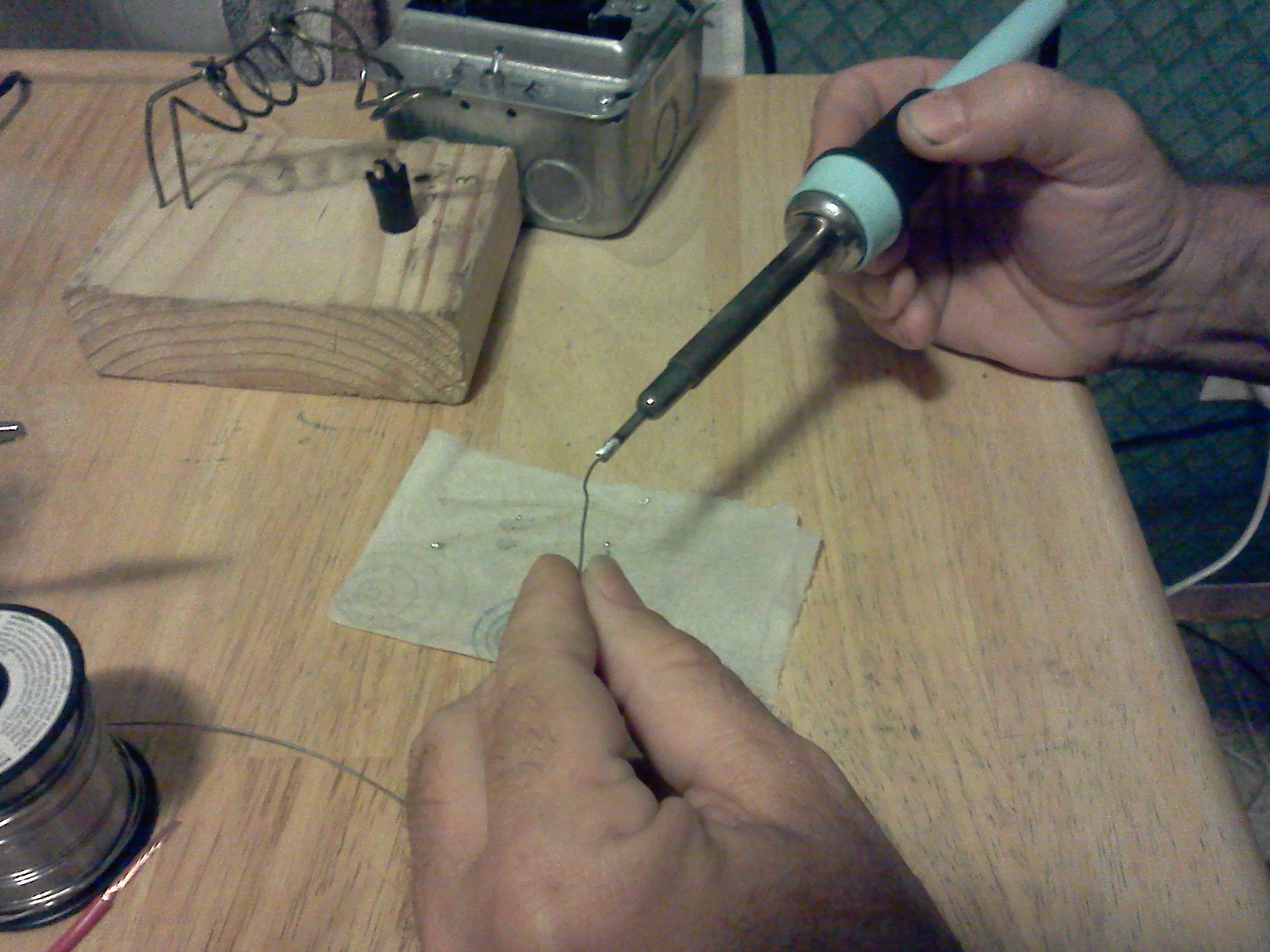
Soldering works best when you make the most surface area contact possible with your iron and whatever you are soldering. This is because it helps the heat transfer process. Place the FLAT side of your solder iron against the largest surface you plan on soldering (the connector). Hold it there for a moment, and while you are holding the iron still in that spot, bring the solder closer to the connector until it is touching the connector. DO NOT TOUCH THE IRON ITSELF WITH THE SOLDER!
 When the connector is sufficiently heated, you will literally see the solder melt from a solid state to a liquid state, and as a liquid - it will FLOW to fill the entire surface of the connector and the wire. At this point, you may move the SOLDER (not the iron) up and down the length of the wire, or the connector (only if necessary) to insure that you have solder everywhere you are trying to put it. Note - you should NOT "glob" solder on. When you are finished, you should be able to see every individual copper wire in a stranded cable, as well as the shape/outline of whatever it is you are soldering. The details of every part of the joint should be very clearly visable, and yet be coated (as if electroplated) with solder. More solder does not make it physically stronger (it is NOT the mechanical bond), nor does it make a better electrical connection - it only costs more money, because it uses more materials.
Once you are satisfied that sufficient solder has been applied, now comes the tricky part of soldering. You must remove the solder away from the joint, then remove the iron away from the joint - all without moving any of the parts you are trying to connect. If you have done correctly - you should have a clean - SHINY solder joint after it cools. If it is not shiny, it is likely a "cold" solder joint. Cold solder joints are formed when the solder isn't high enough temperature to make a good electrical bond - which can often happen if the work is moved mid-cooling process, but can also happen because of not using enough heat, or trying to solder with a dirty iron/connector.
Moving the parts before they are completely cool will cause it to form a "cold" solder joint. Cold solder joints are clearly visable, because when it cools, it will not be shiny, it will be dull in appearance, and may possibly show signs of "cracking","crumbling", or "clumping". If you wind up with a cold solder joint - there is only one fix - resolder it. Not doing so will guarantee electrical failure in your circuit sometime in the future (if not right away).
When you are satisfied that you have made a good solder joint - clean off your solder iron, lightly tin it, and put it away. If you need to make multiple solder joints (as is typically the case), feel free to make all the solder connections you need to before putting your solder iron away. Make sure that all the connections you soldered are clean, shiny, and free from cracks. Use a magnifying glass to look at them if you have to.
Sometimes people make mistakes when soldering (or perhaps you are fixing something someone else put together). You may have to DE-solder a connection or two. There are several methods used for desoldering, but they employ the basic following steps. First, you heat up the iron as if you were soldering, and test to make sure it will melt solder. Then you touch the flat surface of your iron, to the largest surface you are trying to de-solder. Wait until you see the solder flow (it will change in appearance, and you'll see that shiny liquid look). Now gently pull the component loose from the connector. I say gently - some components may require additional effort, but if you have to pull out a crow bar - you are doing something wrong.
If you are dealing with a capacitor (Electrolytics can be pesky ), resistor, or diode, heat and pull one leg at a time. It may help to "rock" the component back and forth as you alternately heat it's connectin point. If you are dealing with parts on a printed circuit board, the pads can be accidentally lifted off either by applying too much heat, or by applying too much force when the component isn't ready to come off yet.
Take great care when removing parts off a printed circuit board. If you are removing a transistor - again rock the part from side to side, alternating heat from one leg to another. If you are removing an integrated circuit of any kind - you need to remove the entire IC all in one movement, or you will physically damage it.
 As an aid to removal of components - there are certain supplies and tools that can make the job easier.
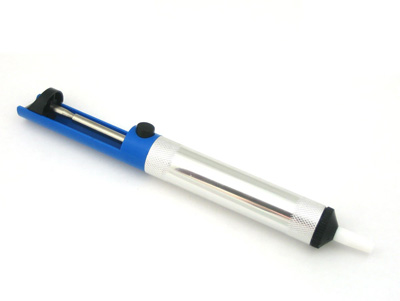
First is a vacuum pump. These come in both manual, and electric types. A manual pump may be just the trick for removing one part, but will give you a hand cramp over time. It is simple to use. Simply ready the pump, heat the connector, then suck. The big advantage to the hand desoldering pump is price. You only have to buy it once, and it isn't very expensive. The disadvantage is that it gets clogged up with solder, and needs to be taken apart and cleaned occasionally, and that if you use it several times a day, your hand can begin to hurt. Electric vacuum pumps take away the problem of the hand cramp - but they still get clogged and need occasional cleaning.
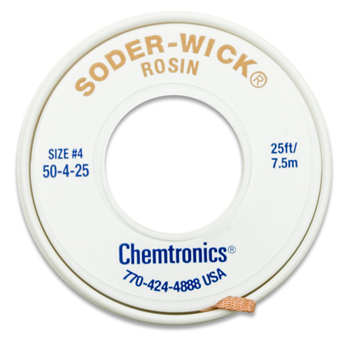 Another tool that is useful for removal of solder is "solder wick". Essentially a braid of very thin wire, solder wick does a fine job of removing solder, and you can use it quite effectively to remove Integrate Circuits and transistors, as well as other components. The big drawback of solder wick is that it is one time use, and expensive. It comes on a spool, and you touch it against the connection you are trying to remove the solder from. You put it BETWEEN the soldered connector, and your soldering iron. When it heats up, it will soak up the solder - then you remove it, cut off what you used, and throw it away. Note it is made of expensive COPPER, and as such - is expensive! If you find a way to reclaim it inexpensivly and easily - please - write me! As a side note - I have used the braid from a spent coaxial cable for the same purpose in the past with great success.
If you are dealing with a capacitor (Electrolytics can be pesky ), resistor, or diode, heat and pull one leg at a time. It may help to "rock" the component back and forth as you alternately heat it's connectin point. If you are dealing with parts on a printed circuit board, the pads can be accidentally lifted off either by applying too much heat, or by applying too much force when the component isn't ready to come off yet.
Take great care when removing parts off a printed circuit board. If you are removing a transistor - again rock the part from side to side, alternating heat from one leg to another. If you are removing an integrated circuit of any kind - you need to remove the entire IC all in one movement, or you will physically damage it.
As an aid to removal of components - there are certain supplies and tools that can make the job easier.First is a vacuum pump. These come in both manual, and electric types. A manual pump may be just the trick for removing one part, but will give you a hand cramp over time. It is simple to use. Simply ready the pump, heat the connector, then suck. The big advantage to the hand desoldering pump is price. You only have to buy it once, and it isn't very expensive. The disadvantage is that it gets clogged up with solder, and needs to be taken apart and cleaned occasionally, and that if you use it several times a day, your hand can begin to hurt. Electric vacuum pumps take away the problem of the hand cramp - but they still get clogged and need occasional cleaning.
Another tool that is useful for removal of solder is "solder wick". Essentially a braid of very thin wire, solder wick does a fine job of removing solder, and you can use it quite effectively to remove Integrate Circuits and transistors, as well as other components. The big drawback of solder wick is that it is one time use, and expensive. It comes on a spool, and you touch it against the connection you are trying to remove the solder from. You put it BETWEEN the soldered connector, and your soldering iron. When it heats up, it will soak up the solder - then you remove it, cut off what you used, and throw it away. Note it is made of expensive COPPER, and as such - is expensive! If you find a way to reclaim it inexpensivly and easily - please - write me! As a side note - I have used the braid from a spent coaxial cable for the same purpose in the past with great success.Now We're Connecting!
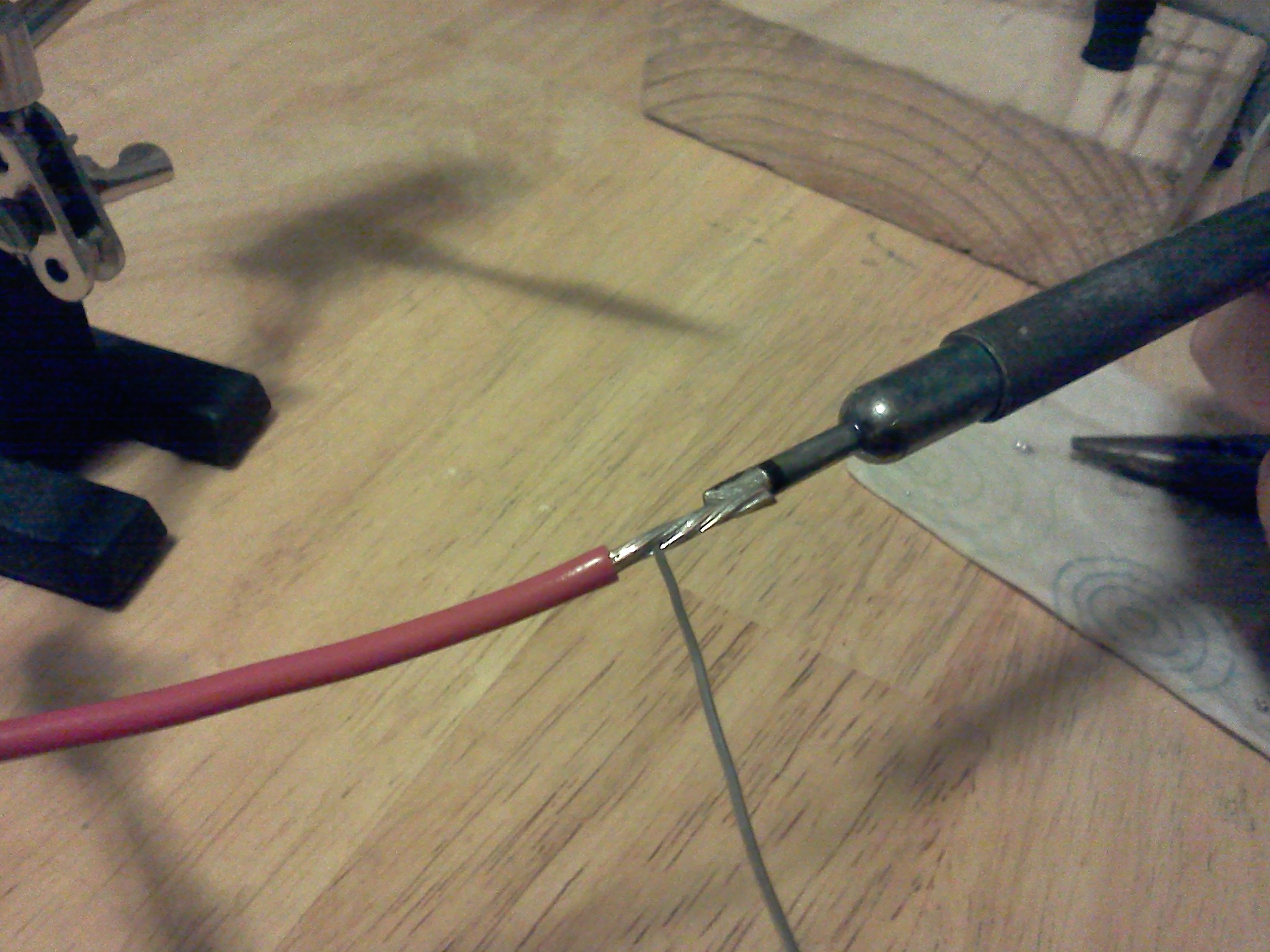
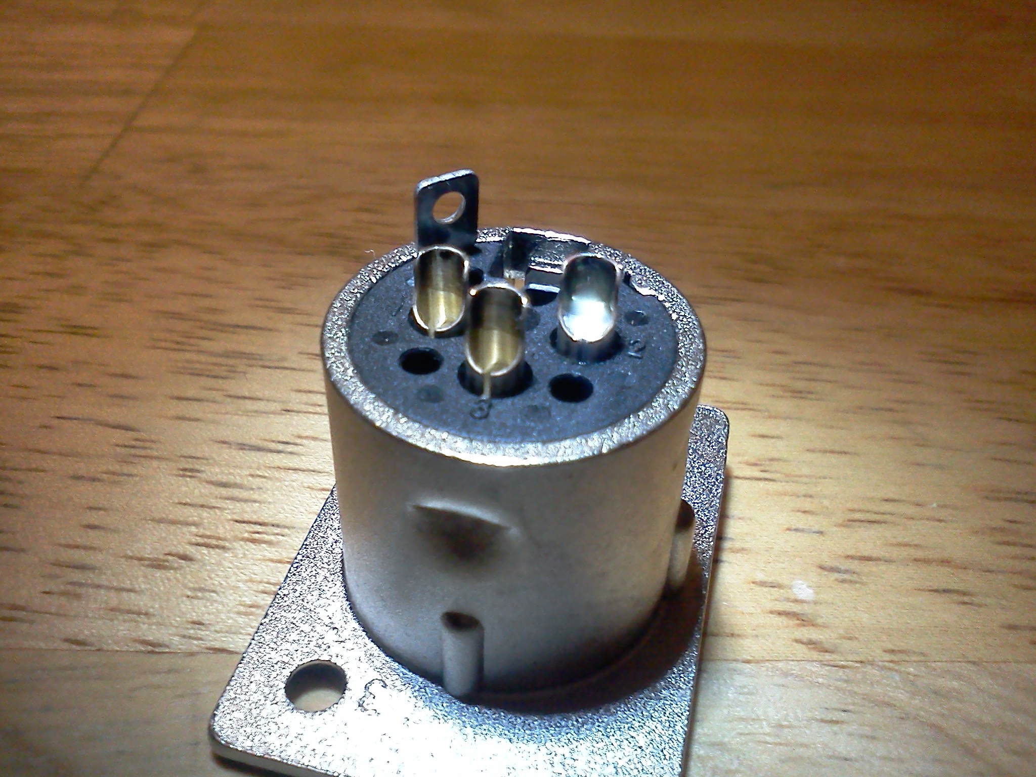 Cup Connectors are an interesting breed of connector. The premise is that you have a copper "cup" which you 'fill' with solder. Note the photo on the left which shows a properly "filled" cup. Do not over-fill the cup to the point where is is overflowing with solder!
Next you tin the wire so that all the individual strands of wire are coated, but not globbed on where you can't see the outline of the individual wires.
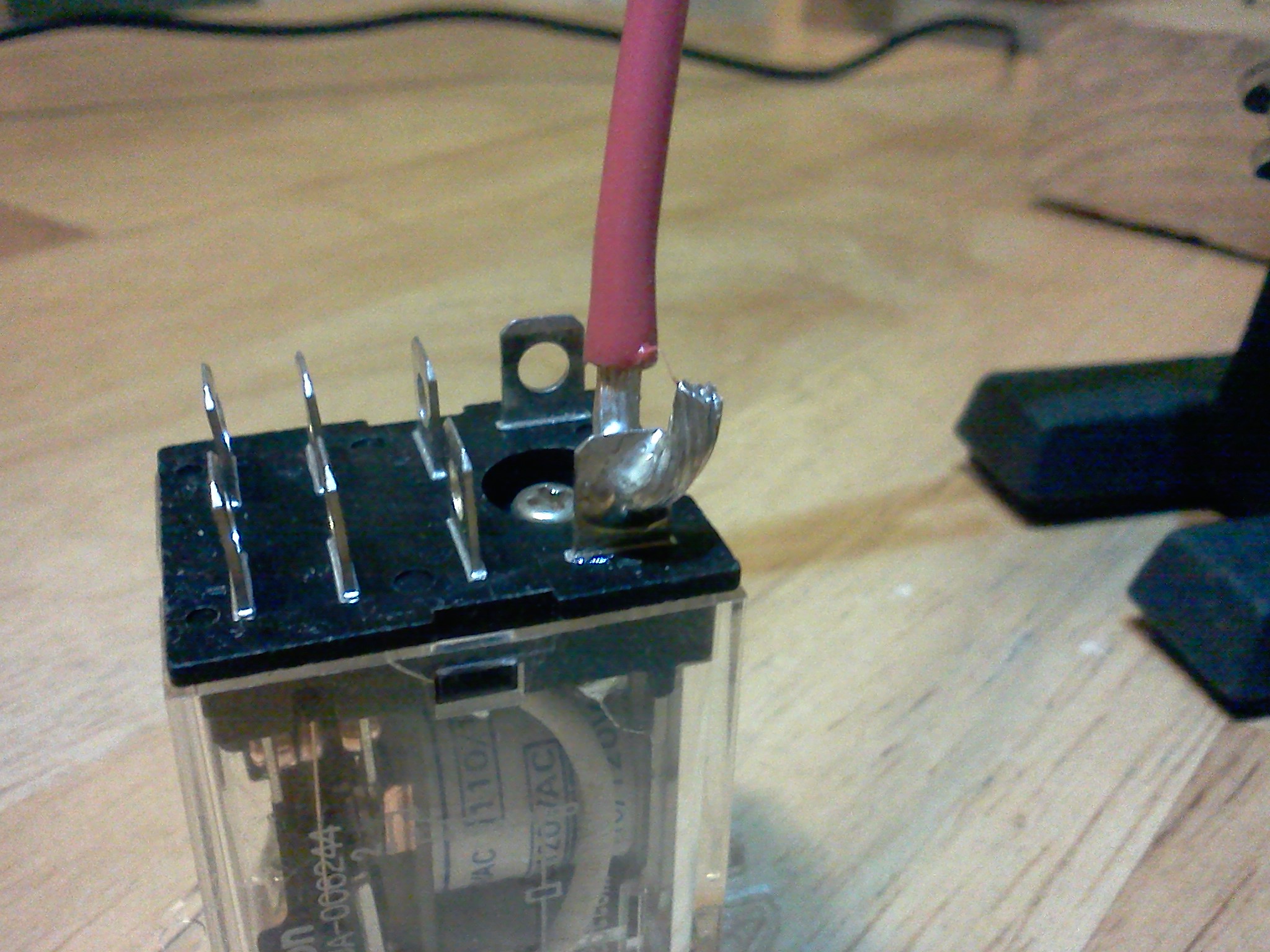
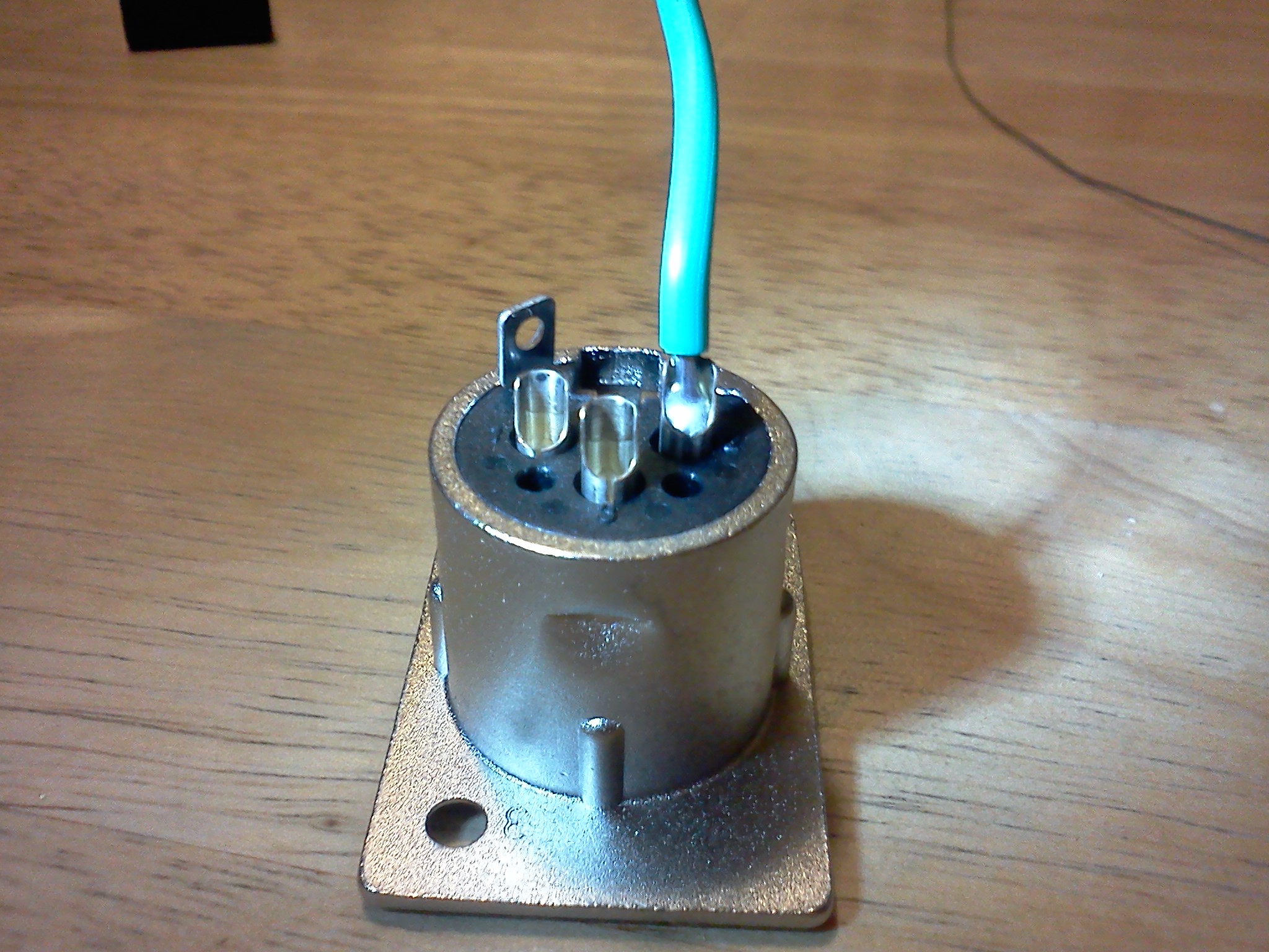 Once the wire is tinned, solder the pre-tinned wire to the pre-filled cup and you are done! (I know the picture on the right is small. click on it if you need a better look.)
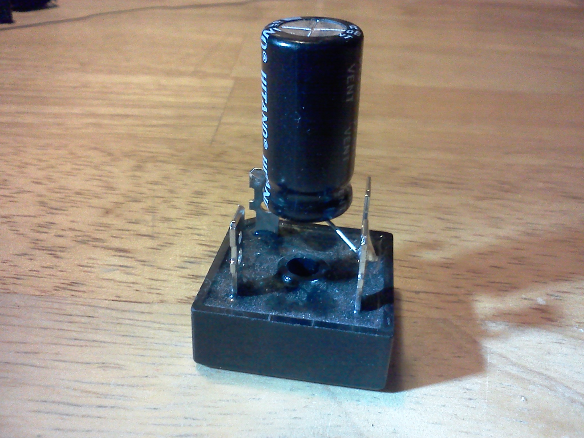 Dead Bug, otherwise known as "ugly construction", is an interesting if not functional method of getting things done. It begins with a central component - usually an integrated circuit (although in this picture it is a full wave bridge recitifier), which is glued, bolted, or otherwise fastened to the chassis of your project box. Then other components are soldered to this central component, using that component as the mechanical foundation for the project.
source:electronicstheory