PRINTRONIX P7000 FAMILY MANUALS
PRINTRONIX P7000 FAMILY MANUALS

P7000
User's Manuals & Quick Start Guide
User's Manual
Quick Reference Guide (EnglishQuick Reference Guide (EMEA)
Quick Reference Guide (Simplified Chinese)
Quick Reference Guide (Korean)
Quick Reference Guide (Japanese)
Quick Setup Guide (English,French,Spanish,Italian)
Quick Setup Guide (S Chinese,Japanese,Korean)
Programmer's Reference Manuals
Coax-Twinax
LinePrinter Plus
IGP-VGL Emulation
ANSI
IPDS Twinax Emulation
Character Sets Reference Manual
LG Emulation
PCL LinePrinter Plus LJ
IGP-PGL Emulation (Simplified Chinese)
PXML
IGP-PGL Emulation
Download your copy from source.
For Maintenance manual get a copy here.
Note:File are in in rar,you need winrar or other unzipping programs.You may only open the files once downloaded all part files.Downloading for the host site require registration to download above two files.


Driver Genius 11 Professional
For downloading driver,here is the driver downloader that will automatically scan the device that matching your products. DRIVER GENIUS PROFESSIONAL install,update,restore and removed invalid drivers.


COMPATIBILITY (OS)
Windows 98/SE/me/2000/XP x64
Windows Server 2003/2008/SERVER 2003/2008 x64
Windows Vista/7 Windows Vista/7 x64
Windows 8/Windows 8 x 64
Driver Genius Professional 11 download here.
Password:r2bcx
Jestine Yong E-books
Jestine Yong e-books
Collect all of these great book of jestine yong and be an expert electronics repairer like jestine.Read and explore of his repair technique by his e-books.You can join and subscribe his blog here and learn a lot from him.These ebooks are scattered in various websites, forums,file storage sites and others and that is available for download for free and many of them are interested because they know how this books are very useful for troubleshooting.

Electronic Servicing and Repair Book Collection


LCD Monitor Repair
ELECTRONICS DISPLAYS
CATHODE RAY TUBE


The electron beam is generated from a filament and electrically charged cathode in the back neck of the CRT. The electron beam is first passed through a control grid. The control grid modulates the intensity of the electron beam. The higher the intensity the brighter the phosphor dot it strikes will glow. Next the beam passes through an accelerating electrode, this will speed up the electron beam. Then the beam passes through a focusing anode. This will focus or tighten the stream of electrons. All of these elements comprise the electron gun structure housed in the neck of the CRT.
Electromagnetic Deflection:
The structure on the neck of the CRT is the yoke. The yoke contains four electromagnets placed around the neck of the CRT in 90 degree increments. By varying the voltage of these four electromagnets, the electron beam can be deflected or bent to reach any location on the phosphor coated screen. A final stage of acceleration is achieved with the high voltage anode. The familiar suction cup wire that attaches to the side of the CRT is connected to this anode. This anode is often a metalized surface on the inside of the picture tube. Many thousands of volts are applied to the anode to pull the electrons towards the phosphor coated screen. Phosphors can be formulated to emit many colors though white and green are the most popular for monochrome screens.

Electrostatic Deflection:
A simpler form of a CRT is formed by replacing the external electromagnetic yoke with four internal electrostatic deflection plates. These plates are placed in pairs on the horizontal and vertical axes. The electron beam is deflected by the application of a positive voltage on the plates as the beam passes through. The beam will bend towards the most positive plate. Though this type of CRT is not as precise as magnetic deflection it is much less expensive and quite effective for simple calculator and oscilloscope displays. Additional circuitry in the calculator can create numbers, letters, and other symbols by using the control grid to turn the electron beam on and off, while simultaneously applying positive potentials to the deflection plates to bend the beam to the desired locations on the screen. Many early desktop calculators like the Friden EC-130 and the Hewlett Packard 9100A used Electrostatic deflection CRTs.Read more
NIXIE TUBE DISPLAY

In a Nixie Tube display each numeral is a complete, lighted cathode in the shape of the numeral. The cathodes are stacked so that different numerals appear at different depths, unlike a planar display in which all numerals are on the same plane relative to the viewer. The anode is a transparent metal mesh wrapped around the front of the display. The tube is filled with the inert gas neon with a small amount of mercury. When an electric potential of 180 to 200 volts DC is applied between the anode and any cathode, the gas near the cathode breaks down and glows. The digits glow with a orange-red color.
The name Nixie came about accidentally. A [Burroughs] draftsman making drawings of the device labeled it NIX I, for Numeric Indicator eXperimental No. 1. His colleagues began referring to it as "Nixie," and the name stuck (Scientific American, June '73, pp. 66).
Interestingly enough the Nixie design is considered "failsafe". If a filament (cathode) fails, the numeral is not illuminated. Whereas, in a seven-segment display if one segment fails, a number other than the intended number may be displayed. The Casio 121-A and the Sharp QT8-B used Nixie tubes.

INCANDESCENT FILAMENT DISPLAY
An Incandescent Filament display is usually housed in a vacuum tube like the either the Nixie tube or the early Vacuum Fluorescent tubes. This display is typically a seven segment style of display where each display segment is formed with a conductive anode tungsten filament. A small voltage placed across a filament will cause it to heat to incandescence. They emit a yellowish-white light that can be filtered to any desired color. The filament voltage (3-5vdc) can also be varied to change the brightness level of the display. The biggest problem with Incandescent displays is they have a slow response time and they consume a large amount of current. A popular version of this type of display was the RCA Numitron. Some early electronic kits used the Incandescent Filament display.
GAS DISCHARGE or PLASMA DISPLAY

Burroughs manufactured a common brand of PDPs called Panaplex II. PDPs were used in many early calculators including CompuCorp's Scientist series.
VACUUM FLUORESCENT DISPLAY MODULE


VACUUM FLUORESCENT DISPLAY TUBE
VFDs were developed in Japan in 1967. Early versions of VFDs were individual digits housed in vacuum tubes like the Nixie tube and Incandescent Filament displays. VFD Phosphors can be formulated to emit red, yellow, and green as well as the more common blue-green color. Later versions would house all of the digits (and other graphics and indicators) in one large glass assembly. Currently VCRs account for 30% of the VFD market and Audio/Video products account for another 30%. Many early series of calculators like the Commodore 412F, Brother 310, and the MITS 816 used the individual digit VFD tubes. Later manufacturers such as TI and Rockwell used the integrated multidigit VFDs in both handhelds and desktops.
ELECTROLUMINESCENT DISPLAY

This type of solid state display can endure extreme conditions with exceptional tolerance to shock, vibration, temperature, and humidity, while response times remain less than one millisecond. I have not seen ELDs used in calculators but they are used in some laptops, office machines and in the cockpit of the Spaceshuttle. They are also used to backlight LCD panels.
LED DISPLAYS

A Light Emitting Diode (LED) is an special type of diode that emits light when electricity applied to it's anode and cathode. A typical LED requires about 3 volts DC at 10 milliamps to begin emitting light. LEDs usually produce red light but yellow, green and blue versions are also now available. The LED was first marketed by Texas Instruments around 1962. LED displays (7 or more individual LEDs) were introduced around 1967 but were very expensive. Calculators used LEDs that were arranged to form either a seven-segment display or a dot-matrix display.

LED TYPES
Early seven segment displays formed each segment with many LEDs, later seven-segment displays would use one LED per segment with a light pipe to spread it's light across the segment. Also early LED displays were made small in order to keep power consumption down. A clear plastic bubble lens was fabricated into the package to magnify the display for easier viewing.

NUMERIC REPRESENTATION
The dot-matrix style of display would form characters shaped similarly to that of a dot-matrix printer. A dot matrix of 4x7 or 5x7 is typically used. Notice how the 4x7 matrix makes up for the missing 5th column by slightly slanting the columns. LEDs require much more power than LCDs and are more expensive to manufacture. This is the simple reason for their demise from being used in calculators.
LIQUID CRYSTAL DISPLAY

A LCD consists of two plates of glass, sealed around the perimeter, with a layer of liquid crystal fluid between them. Transparent, conductive electrodes are deposited on the inner surfaces of the glass plates. The electrodes define the segments, pixels, or special symbols of the display. Next a thin polymer layer is applied on top of the electrodes. The polymer is etched with channels in order to align the twist orientation of the LC's helix shaped molecules. Finally, polarizing films are laminated to the outer surfaces of the glass plates at 90 degree angles. Normally, two polarizing films at 90 degrees should be dark, preventing any transmission of light but due to the ability of LC to rotate polarized light the display appears clear. When AC voltage is passed through the LC, the crystals within this field align so that the polarized light is not twisted. This allows the light to be blocked by the crossed polarizers thus making the activated segment or symbol to appear dark.
LCD THEORY OF OPERATION

Many other types of LCD displays are being developed for the laptop and CRT replacement market including full color versions. These include double and triple twisted nematic (DSTN and TSTN) displays and the Active-matrix Thin-film Twisted Nematic and Metal-Insulated-Metal Twisted Nematic (TFT-TN and MIM-TN) displays. Unfortunately these advanced display are too expensive for most of the calculator market. TN LCDs almost completely dominate todays calculator market due to their extremely low power requirements, thin size, and low cost.

Epson Stylus NX420 Series Manuals
Epson nx420 series

See Products Specification.
This manual Includes the following:
*Quick Guide
*Wireless Network Setup
*Basic Copying, Printing, and Scanning
*Maintenance
*Solving Problems
Download your copy here.
Driver download.
_____________________________________________________________________
Related Post:
Epson NX420 Error Codes and Solutions
Epson LX-300+ Service Manual


M0del: Epson LX-300+
download now
Need where to find a download link?,just click on the picture above to download of free service manual.
Hammer Voltage Fault(1 and 2)
Hammer voltage fault problem is a fault usually comes from a line matrix printer model tally genicom 63** and 62** series.When this trouble appear in control panel,a high resistance coil fault has likely occurred in one or more of the hammer coils.In a 63** series a dual mosfet transistor coil driver in a controller board usually found a problem.


Model: Tally Genicom
T6218
T6306
T6312
In my repair of this trouble,in 63** series,i usually found a defective dual N-channel mosfet transistor(FDS3890),cause by a burnt hammer coils and a shorted or defective hammer bank cables.You can also take a look of hammer voltage faults diagnostic aid table below.

Read this solution from the printer place.

62** series 63** series
Model: Tally Genicom
T6212
T6215T6218
T6306
T6312
In my repair of this trouble,in 63** series,i usually found a defective dual N-channel mosfet transistor(FDS3890),cause by a burnt hammer coils and a shorted or defective hammer bank cables.You can also take a look of hammer voltage faults diagnostic aid table below.

Read this solution from the printer place.
This problem is often caused when one or more of the four ribbon shield guide brackets is mispositioned leaving little or no clearance between it and the coil board assembly. When contact is made between the soldered coil terminal points on the underside of the coil board and the ribbon shield guide, a short occurs. This leads to the possibility of destroyed transistors on the hammer driver board which produces the “hammer voltage fault”.
A visual inspection will determine whether there is a clearance problem between the terminals on the coil board and the ribbon shield guide. If about 0.010” or more (definite clearance by eye) cannot be verified, replace the hammer driver board (the transistor is blown anyhow - PN 082578). At the same time, ohm out the coil board to check for coil damage so that it can be replaced also, if it is damaged (PN 083685).
Prior to reassembly, wrap Kapton tape (or a similar durable insulation type tape) around the ribbon shield guide bracket to prevent metal-to-metal contact.
Obviously, this is most easily accomplished with the hammer driver board and the coil board removed. Watch as you mount the hammer driver board and bias it (move it against the screws) so that there is maximum clearance.
JVC Chassis_ga2

Model: AV-21D13
AV-21D33
AV-20N13
AV-20N33
Need where to find a download link?,just click on the picture above to download of free service manual.
Daewoo chassis CN-100
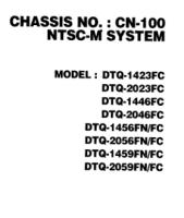
Model: DTQ-1423FC
DTQ-2023FC
DTQ-1446FC
DTQ-2046FC
DTQ-145FN/FC
DTQ-2056FN/FC
DTQ-1459FN/FC
DTQ-2059FN/FC
Need where to find a download link?,just click on the picture above to download of free service manual.
APC BACK UPS PRO 650

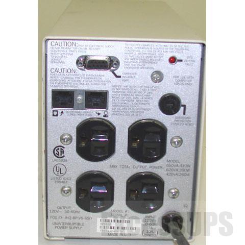
APC BACK-UPS PRO 650 650VA 420W BP650S Refurbished
Click here to download user manual.
OUTPUT
Output power capacity 650 VA
Output power capacity 420 Watts
Output Connections 4 x 15A (Standard Plug)
INPUT
Nominal input voltage 120V
Input Connection Type NEMA 5-15P (Standard Plug)
Replacement battery cartridge RBC4
Typical backup time at half load 19.2 minutes
Typical backup time at full load 8.4 minutes
PHYSICAL
Height x Width x Depth (in) 6 x 4 x 15
Electronics Tutorials videos
Basic Electronics Bridge Rectifier tutorial
Voltage regulator tutorial & USB gadget charger circuit
How To Test a Transistor
Power Supply Circuit
ATX POWER SUPPLY 200W
Contents:
> Schematic diagram of 200w atx power supply
> Standby mode
> Function of running power supply
> Output voltage stabilization
> Power Good
> +3.3V Voltage Stabilization
> Over-voltage Circuit
> Links
> Atx Power Connector

This power supply circuit uses chip TL494. Similar circuit is used in the most power supplies with output power about 200W.Device use push-pull transistor circuit with regulation of output voltage.Line voltage goes through input filter circuit (C1, R1, T1, C4, T5) to the bridge rectifier. When voltage is switched from 230V to 115V, then rectifier works like a doubler. Varistors Z1 and Z2 have overvoltage protect function on the line input.
Thermistor NTCR1 limits input current until capacitors C5 and C6 are charged. R2 and R3 are only for discharge capacitors after disconnecting power supply. When power supply is connected to the line voltage, then at first are charged capacitors C5 and C6 together for about 300V.
Then take a run secondary power supply controlled by transistor Q12 and on his output will be voltage. Behind the voltage regulator IC3 will be voltage 5V, which goes in to the motherboard and it is necessary for turn-on logic and for "Wake on something" functions.
Next unstabilized voltage goes through diode D30 to the main control chip IC1 and control transistors Q3 and Q4. When main power supply is running, then this voltage goes from +12V output through diode D.
In a normal operation is power supply controlled by IC1. When transistors Q1 and Q2 are closed, then Q3 and Q4 are opened. When we want to open one from power transistors (Q1, Q2), then we have to close his exciting transistor (Q3, Q4). Current goes via R46 and D14 and one winding T2. This current excite voltage on base of power transistor and due to positive feedback transistor goes quickly to saturation. When the impulse is finished, then both exciting transistors goes to open. Positive feedback dissapears and overshoot on the exciting winding quickly closes power transistor. After it is process repetead with second transistor. Transistors Q1 and Q2 alternately connects one end of primary winding to positive or negative voltage. Power branch goes from emitor of Q1 (collector Q2) through the third winding of exciting transformer T2. Next throug primary winding of main transformer T3 and capacitor C7 to the virtual center of supply voltage.
This voltage is rated from voltage before coil, pulse-width and duration cycle. On the output behind the rectifier diodes is a common coil for all voltages. When we keep direction of windings and winding number corresponding to output voltages, then coil works like a transformer and we have compensation for irregular load of individual voltages.
In a common practise are voltage deviations to 10% from rated value. From the internal 5-V reference regulator (pin 14 IC1) goes reference voltage through the voltage divider R24/R19 to inverting input(pin 2) of error amplifier. From the output of power supply comes voltage through divider R25,R26/R20,R21 to the non inverting input (pin 1). Feedback C1, R18 provides stability of regulator. Voltage from error amplifier is compared to the ramp voltage across capacitor C11.
When the output voltage is decreased, then voltage on the error amplifier is toodecreased. Exciting pulse is longer, power transistors Q1 and Q2 are longer opened, width of pulse before output coil is grater and output power is increased. The second error amplifier is blocked by voltage on the pin 15 IC1.
For example when I by mistake short-circuit -5V with +5V, then positive voltage goes across D10, R28, D9 to the base Q6. This transistor is now opened and opens Q5. +5V from pin 14 IC1 comes across diode D11 to the pin 4 IC1 and power supply is blocked. Beyond that goes voltage again to base Q6. Power supply is still blocked, until he is disconnected from power line input.
Then take a run secondary power supply controlled by transistor Q12 and on his output will be voltage. Behind the voltage regulator IC3 will be voltage 5V, which goes in to the motherboard and it is necessary for turn-on logic and for "Wake on something" functions.
Next unstabilized voltage goes through diode D30 to the main control chip IC1 and control transistors Q3 and Q4. When main power supply is running, then this voltage goes from +12V output through diode D.
Stand-By mode
In stand-by mode is main power supply blocked by positive voltage on the PS-ON pin through resistor R23 from secondary power supply. Because of this voltage is opened transistor Q10, which opens Q1, which applies reference voltage +5V from pin 14 IO1 to pin 4 IO1. Switched circuit is totally blocked. Tranzistors Q3 and Q4 are both opened and short-circuit winding of auxiliary transformer T2.Due to short-circuit is no voltage on the power circuit. By voltage on pin 4 we can drive maximum pulse-width on the IO1 output. Zero voltage means the highest pulse-width. +5V means that pulse disappear.Now we can explain function of running power supply.
Somebody pushes the power button on computer. Motheboard logic put to ground input pin PS-ON. Transistor Q10 closes and next Q1 closes. Capacitor C15 begins his charging through R15 and on the pin 4 IC1 begins decrease voltage to zero thanks to R17. Due to this voltage is maximum pulse-width continuosly increased and main power supply smoothly goes run.In a normal operation is power supply controlled by IC1. When transistors Q1 and Q2 are closed, then Q3 and Q4 are opened. When we want to open one from power transistors (Q1, Q2), then we have to close his exciting transistor (Q3, Q4). Current goes via R46 and D14 and one winding T2. This current excite voltage on base of power transistor and due to positive feedback transistor goes quickly to saturation. When the impulse is finished, then both exciting transistors goes to open. Positive feedback dissapears and overshoot on the exciting winding quickly closes power transistor. After it is process repetead with second transistor. Transistors Q1 and Q2 alternately connects one end of primary winding to positive or negative voltage. Power branch goes from emitor of Q1 (collector Q2) through the third winding of exciting transformer T2. Next throug primary winding of main transformer T3 and capacitor C7 to the virtual center of supply voltage.
Output voltage stabilisation
Output voltages +5V and +12V are measured by R25 and R26 and their output goes to the IC1. Other voltages are not stabilised and they are justified by winding number and diode polarity. On the output is necessary reactance coil due to high frequency interference.This voltage is rated from voltage before coil, pulse-width and duration cycle. On the output behind the rectifier diodes is a common coil for all voltages. When we keep direction of windings and winding number corresponding to output voltages, then coil works like a transformer and we have compensation for irregular load of individual voltages.
In a common practise are voltage deviations to 10% from rated value. From the internal 5-V reference regulator (pin 14 IC1) goes reference voltage through the voltage divider R24/R19 to inverting input(pin 2) of error amplifier. From the output of power supply comes voltage through divider R25,R26/R20,R21 to the non inverting input (pin 1). Feedback C1, R18 provides stability of regulator. Voltage from error amplifier is compared to the ramp voltage across capacitor C11.
When the output voltage is decreased, then voltage on the error amplifier is toodecreased. Exciting pulse is longer, power transistors Q1 and Q2 are longer opened, width of pulse before output coil is grater and output power is increased. The second error amplifier is blocked by voltage on the pin 15 IC1.
PowerGood
Mainboard needs "PowerGood" signal. When all output voltages goes to stable, then PowerGood signal goes to +5V (logical one). PowerGood signal is usually connected to the RESET signal.+3.3V Voltage stabilisation
Look at circuit connected to output voltage +3.3V. This circuit makes additional voltage stabilisation due to loss of voltage on cables. There are one auxiliary wire from connector for measure 3.3V voltage on motherboard.Overvoltage circuit
This circuit is composed from Q5, Q6 and many discrete components. Circuit guards all of output voltages and when the some limit is exceeded, power supply is stopped.For example when I by mistake short-circuit -5V with +5V, then positive voltage goes across D10, R28, D9 to the base Q6. This transistor is now opened and opens Q5. +5V from pin 14 IC1 comes across diode D11 to the pin 4 IC1 and power supply is blocked. Beyond that goes voltage again to base Q6. Power supply is still blocked, until he is disconnected from power line input.
Links
- http://www.belza.cz/swmodeps/compow1.htm (Czech language only)
- http://www.belza.cz/swmodeps/compow2.htm (Czech language only)
- http://www.epanorama.net/links/psu_computer.html Computer Power Supply Page
- http://www.webx.dk/oz2cpu/radios/psu-pc1.htm Power supply modification
ATX Power Connector
| Pin | Signal | Color 1 | Color 2 | Pin | Signal | Color 1 | Color 2 |
|---|---|---|---|---|---|---|---|
| 1 | 3.3V | orange | violet | 11 | 3.3V | orange | violet |
| 2 | 3.3V | orange | violet | 12 | -12V | blue | blue |
| 3 | GND | black | black | 13 | GND | black | black |
| 4 | 5V | red | red | 14 | PS_ON | green | grey |
| 5 | GND | black | black | 15 | GND | black | black |
| 6 | 5V | red | red | 16 | GND | black | black |
| 7 | GND | black | black | 17 | GND | black | black |
| 8 | PW_OK | grey | orange | 18 | -5V | white | white |
| 9 | 5V_SB | violet | brown | 19 | 5V | red | red |
| 10 | 12V | yellow | yellow | 20 | 5V | red | red |
source:pavouk
Subscribe to:
Posts (Atom)